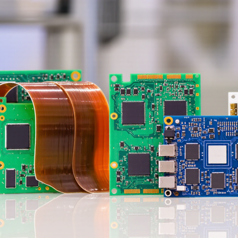
2026 Best Circuit Board Types for Global Buyers

Choosing the right circuit board in 2026 is no longer a simple price comparison. Global buyers must weigh electrical performance, production volume, environmental conditions, delivery risk, and supplier reliability. A rigid FR-4 board may suit control panels, while flexible and rigid-flex boards support compact medical devices, sensors, and moving assemblies. HDI designs can save space, but they demand tighter manufacturing control and more careful inspection.

“Quality is not an accident; it is the result of controlled processes,” says John W. Mitchell, President and CEO of IPC. This principle matters when comparing board suppliers across regions. Experienced buyers should review IPC-2221 design guidance, IPC-A-600 acceptance criteria, UL recognition, RoHS and REACH documentation, and complete material traceability. Factory audits, solderability checks, impedance testing, and thermal-cycle reports can reveal weaknesses that a polished website hides.

There is no universal winner.

This guide examines the best circuit board types for global buyers in 2026, including rigid, flexible, rigid-flex, HDI, metal-core, and ceramic options. Each type has a practical place, but each also carries trade-offs. A low quotation may conceal higher testing costs, longer approvals, or field failures. I have seen specifications look complete until stack-up details and surface-finish requirements were missing. That is an uncomfortable lesson. Buyers should challenge assumptions, compare samples, and confirm production controls before placing large orders. The best choice is not always the most advanced board. It is the board that performs reliably, meets documented requirements, and remains supportable throughout its service life.

2026 Best Circuit Board Types for Global Buyers

Circuit Board Fundamentals and Key Selection Criteria for Global Buyers

Circuit board selection starts with function, not price. A single-sided board suits simple controls and low-density wiring. Double-sided boards support more components and shorter routing paths. Multilayer boards manage complex power, signal, and grounding requirements. Rigid-flex designs reduce connectors in moving equipment. HDI boards support compact products, but they demand tighter manufacturing control.

Trace width matters. Copper thickness affects current capacity and heat. High-speed signals need controlled impedance and careful layer planning. Engineers should check dielectric properties, via structures, and return paths before ordering. FR-4 remains practical for many applications, while specialized materials may suit high-frequency or high-temperature environments. I have seen teams choose thinner boards for size, then struggle with warping during assembly.

Global buyers should compare layer count, minimum trace spacing, tolerance data, and test coverage. Ask for material certificates, inspection records, and electrical test methods. Environmental exposure also matters. Moisture, vibration, salt air, and repeated temperature changes can shorten board life. Safety requirements vary by market, so documentation must match the destination. Delivery planning deserves equal attention. A technically suitable board can still fail a launch if tooling, sampling, or replacement capacity is unclear. I still over-specify some designs when risk is uncertain. That costs money. Yet underestimating thermal or mechanical stress costs more. Capture those assumptions in writing, and review them with the manufacturer before production.

Single-Layer, Double-Layer, and Multilayer PCB Applications

2026 Best Circuit Board Types for Global Buyers

Single-Layer, Double-Layer, and Multilayer PCB Applications

Single-layer PCBs suit simple products such as LED panels, basic sensors, and household timers. Their open layout supports easy inspection and lower production costs. Keep it simple. They work best when routing is short and component density remains low. However, single-layer boards offer limited flexibility for compact designs. Global buyers should confirm copper thickness, board size, and regional safety requirements before ordering.

Double-layer PCBs handle more connections without a dramatic cost increase. They support control panels, power supplies, measuring devices, and small communication equipment. Plated through-holes connect both copper surfaces and improve routing options. Space matters. In field evaluations, poor grounding often causes more trouble than the layer count itself. Designers should check heat paths, connector placement, and electromagnetic noise. A cheaper board can become expensive after repeated testing.

Multilayer PCBs serve advanced equipment with dense circuits, processors, memory, and high-speed signals. Internal power and ground planes can reduce interference and shorten current paths. Careful stack-up design is essential. Buyers should request impedance data, drilling tolerances, material specifications, and test records. Regional compliance documents also need verification. More layers do not automatically mean better performance. I have seen overbuilt designs waste space and budget. A practical review should balance signal needs, thermal behavior, production yield, and expected service conditions.

Rigid, Flexible, and Rigid-Flex Circuit Boards Compared

2026 Best Circuit Board Types for Global Buyers

Rigid, Flexible, and Rigid-Flex Circuit Boards Compared

Rigid circuit boards remain practical for control panels, industrial equipment, and fixed electronic assemblies. They provide stable mechanical support and usually simplify automated assembly. Their predictable structure helps engineers control impedance, thermal paths, and component placement. However, they need more enclosure space and cannot tolerate repeated bending.

Flexible circuit boards use bendable dielectric materials and suit cameras, wearable devices, and compact products. They can reduce wiring, connectors, and overall weight. A well-designed flex circuit also folds around tight corners, like a ribbon inside a small hinge. Still, sharp bends, poor strain relief, and excessive copper density can cause early failure.

Rigid-flex boards combine firm mounting zones with flexible interconnections. This design can remove several connectors and improve signal reliability in moving products. It often costs more and requires stricter stack-up control. I have seen teams select rigid-flex too early, before confirming their bend radius and assembly method. That mistake can create avoidable tooling changes.

Global buyers should compare operating temperature, layer count, bend cycles, material availability, and inspection records. Ask for cross-section reports, electrical test results, and process capability data. Supplier communication matters when specifications cross languages and time zones. A clean drawing is not enough. Review connector stress, moisture exposure, and repair limitations before approval. Even experienced teams sometimes underestimate packaging damage during international shipping.

2026 Best Circuit Board Types for Global Buyers - Rigid, Flexible, and Rigid-Flex Circuit Boards Compared

Evaluation Dimension Rigid Circuit Boards Flexible Circuit Boards Rigid-Flex Circuit Boards
Basic Construction Solid laminate structure, commonly based on glass-reinforced epoxy materials such as FR-4. Thin bendable structure using flexible dielectric films, commonly polyimide, with copper circuitry. Integrated construction combining rigid sections with one or more flexible circuit sections.
Mechanical Form Flat and dimensionally stable; not intended for repeated bending. Can be folded, bent, or shaped to fit three-dimensional product assemblies. Provides rigid component-support areas and flexible interconnect areas within one circuit assembly.
Typical Thickness Approximately 0.8–3.2 mm for many standard multilayer designs; special constructions may be thinner or thicker. Approximately 0.05–0.5 mm for many single- and multilayer designs, depending on copper, coverlay, stiffeners, and layer count. Typically about 0.3–2.0 mm across rigid and flexible zones, with local thickness varying by construction.
Bending Capability Generally unsuitable for dynamic bending; limited forming may be possible only with specially engineered materials. Suitable for static folds and, when specifically designed, repeated dynamic flexing. Flexible zones support bending, while rigid zones retain component placement and structural support.
Minimum Bend Radius Not normally specified for routine applications; bending can crack copper, solder joints, or laminate. Common design guidance is about 6–10 times the finished flex thickness for static bends; dynamic applications may require a larger radius and qualification testing. Often designed around approximately 8–12 times the flexible-zone thickness, subject to layer count, copper type, bend direction, and application life.
Layer-Count Availability Broadest range, from single-layer boards to high-layer-count multilayer structures. Available from single-layer to multilayer constructions, but layer count and stack-up complexity can reduce flexibility. Supports multilayer rigid and flexible sections, but stack-up transitions require specialized engineering.
Interconnection Density High density is achievable with fine lines, microvias, and advanced multilayer structures. High interconnection density can be achieved while reducing connectors and cable assemblies. High system-level density because multiple board-to-board connectors and cable interfaces may be eliminated.
Assembly and Connector Count May require separate cables, headers, or connectors between mechanically separated boards. Can replace some cable assemblies and connectors, depending on mechanical and electrical requirements. Often minimizes connector count by integrating rigid boards and flexible interconnects into one assembly.
Space and Weight Efficiency Good for flat layouts, but separate boards, cables, and connectors can increase system volume and mass. Excellent for compact, lightweight, and folded product architectures. Very good system-level packaging efficiency, especially where several rigid boards would otherwise be connected by cables.
Thermal Management Usually the easiest of the three types to integrate with heat-spreading structures and metal-core constructions. Thermal dissipation is more constrained by thin materials and limited copper area; thermal design requires careful analysis. Rigid zones can support thermal solutions, while flexible zones require attention to copper distribution and heat concentration.
Component Mounting Well suited to standard surface-mount and through-hole assembly on stable flat surfaces. Components are commonly mounted on rigidized or stiffened areas; unsupported flex zones are generally not used for heavy components. Components are mounted primarily on rigid sections, with flexible sections used for routing and movement.
Manufacturing Complexity Lowest overall complexity for conventional designs and high-volume standard layouts. Higher complexity due to flexible materials, coverlays, stiffeners, bend zones, and handling requirements. Highest complexity because rigid and flexible material systems, registration, lamination, and transition areas must be controlled together.
Relative Cost per Board Usually the lowest-cost option for standard designs and large production volumes. Typically higher than standard rigid boards because of specialized materials and processing. Usually the highest initial board cost, although total system cost may decrease by reducing connectors, cables, assembly steps, and space.
Prototype and Tooling Considerations Generally straightforward to prototype using common fabrication processes. Prototype cost can be affected by coverlay tooling, stiffeners, bend requirements, and material availability. Requires detailed stack-up, bend-zone, tooling, and assembly planning before production release.
Reliability Risks Thermal cycling, plated-through-hole fatigue, delamination, warpage, and solder-joint stress are common concerns. Copper cracking from over-bending, coverlay damage, flex-zone fatigue, and stiffener transitions require control. Stress concentration at rigid-to-flex transitions, bend damage, delamination, and assembly strain require specialized validation.
Typical Operating Temperature Determined by laminate, copper, solder mask, components, and assembly requirements; common FR-4 systems are often selected for approximately −40°C to +130°C applications when properly specified. Determined by the flexible dielectric, adhesive system, coverlay, copper, and components; polyimide-based constructions can support wide temperature ranges when qualified. Limited by the lowest-rated material or component in the combined rigid-flex stack-up; the rigid and flexible sections should be qualified together.
Impedance-Control Capability Strong capability with controlled dielectric thickness, copper geometry, and multilayer stack-up design. Achievable, but thin dielectric layers, bend geometry, copper variation, and dimensional changes require closer control. Achievable across rigid and flexible sections, but impedance continuity through transitions requires detailed stack-up modeling.
Environmental Resistance Good when the laminate, solder mask, finish, and enclosure are selected for moisture, chemicals, vibration, and temperature exposure. Good when properly protected, but exposed bend zones and coverlay edges may need additional mechanical or environmental protection. Can provide strong environmental performance, but rigid-to-flex transitions and dynamic movement areas need application-specific sealing and testing.
Best-Fit Applications Computing equipment, industrial controls, power electronics, automotive modules, instrumentation, and general embedded electronics. Compact wearables, cameras, displays, medical instruments, printers, sensors, and products requiring repeated or shaped movement. Compact medical devices, aerospace electronics, automotive modules, cameras, high-density instrumentation, and assemblies with limited space.
Recommended Buyer Priority Choose when low cost, easy sourcing, thermal robustness, and conventional assembly are the primary objectives. Choose when weight, thickness, movement, folding, or cable replacement is more important than the lowest unit price. Choose when packaging efficiency, reduced interconnections, reliability, and lower system assembly complexity justify a higher board price.

Technical values are typical design ranges rather than universal limits. Final material selection, bend radius, temperature rating, impedance, reliability, and manufacturing tolerances should be confirmed through the applicable design rules, material datasheets, supplier capability, and product qualification testing.

High-Speed, High-Density, and HDI PCB Technologies for 2026

For global buyers, 2026 PCB selection will center on speed, density, and reliability. WSTS’s Spring 2025 forecast expects semiconductor sales to grow 11.2% in 2025 and 8.5% in 2026. That demand will push more designs toward high-speed and high-density boards. Prismark’s 2024 PCB industry analysis placed the global market near US$74 billion, with mid-single-digit growth expected. The exact forecast may shift. Supply cycles remain difficult to predict.

High-speed boards need controlled impedance, low-loss materials, shorter via stubs, and careful back-drilling. At 56G or 112G PAM4 links, small geometry changes can weaken the eye opening. Designers should request insertion-loss data, TDR reports, and verified stackup drawings. High-density interconnect boards add microvias and sequential lamination. They save routing space, but they demand tighter registration control and stronger process records. IPC technical guidance repeatedly emphasizes fabrication capability, thermal reliability, and test documentation.

Not every dense stackup is better. I have seen compact layouts create heat problems and difficult repairs. That lesson still deserves attention. Buyers should compare layer count, copper thickness, dielectric performance, via reliability, and lot traceability. HDI can reduce board size, yet it may increase inspection needs and manufacturing cost. A practical 2026 specification should include material certificates, impedance tolerances, thermal cycling results, and clear acceptance limits. Fancy geometry is not proof of dependable performance.

How to Choose PCB Types by Industry, Budget, and Compliance Needs

Choosing a PCB type starts with the product’s working environment, not its catalog name. Consumer devices often suit rigid boards with stable layouts and moderate heat. Wearables may need flexible or rigid-flex construction around hinges, batteries, and curved housings. Industrial controllers usually demand stronger materials, wider temperature ratings, and dependable signal performance. High-speed equipment requires controlled impedance and careful layer planning. Medical and automotive projects need documented traceability, testing, and sector-specific compliance evidence. These requirements can raise costs, but they reduce field failures.

Budget decisions should include assembly, inspection, tooling, maintenance, and possible redesigns. A two-layer board may suit a simple sensor, while four or more layers can reduce noise and routing problems. Ask suppliers for material specifications, test reports, tolerance data, and production records. Check whether the PCB meets relevant safety, environmental, and electromagnetic requirements in each target market. Compliance is not a final stamp. It affects materials, spacing, finishes, and testing from the beginning. Teams often focus on unit price and overlook shipping damage or difficult rework. That lesson can be expensive.

Tips: Define temperature, vibration, current, frequency, and enclosure limits before requesting quotes. Compare total ownership cost, not only board price. Keep one qualified alternative material or process. It may protect schedules. Still, assumptions can fail. Recheck every requirement with a test sample before full production.

2026 Best Circuit Board Types for Global Buyers — How to Choose PCB Types by Industry, Budget, and Compliance Needs

The chart uses a relative suitability index from 1 to 5, based on typical design requirements such as cost efficiency, mechanical flexibility, thermal management, miniaturization, reliability, and compliance pressure. Actual selection should be validated against operating conditions, production volume, certification requirements, and design specifications.