How to Use Multi Circuit Boards Effectively in Your Projects?
Multi circuit boards are essential tools in modern electronics. They allow for complex designs and efficient space utilization. Understanding their effective use can enhance your projects significantly.
When designing with multi circuit boards, consider your specific needs. Each project may require a different approach. Balancing functionality and space can be challenging. Not every design will meet your expectations, and you may need to rethink your initial plans.
Testing and iteration are crucial. You may find that certain configurations do not work as intended. This can be frustrating, but it is part of the learning process. By carefully analyzing your results, you can refine your approach. Embrace the imperfections and learn from them.
Understanding Multi Circuit Boards and Their Advantages
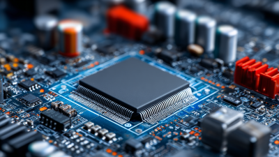
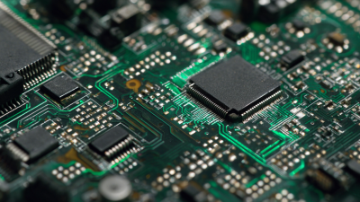
Multi circuit boards are an excellent solution for modern electronic projects. These boards allow multiple circuits to exist in a compact space. This leads to efficient designs. They save time and resources. Many engineers prefer them for complex applications. Their versatility can greatly enhance functionality.
One major advantage is reduced size. Multi circuit boards occupy less physical space. This is crucial for small devices like wearables. However, working with them can be challenging. Proper planning is essential. Wiring mistakes can lead to circuit failures. It’s important to double-check connections. Sometimes, components are too close. This can cause interference and other issues.
Another benefit is improved performance. Multi circuit boards can handle more tasks simultaneously. They promote faster data transfer. Nevertheless, they require precise software integration. If not managed well, this complexity can create problems. Testing is vital to ensure everything works correctly. With challenges come opportunities for growth as developers refine their skills.
Identifying Suitable Projects for Multi Circuit Board Application
In the world of electronics, multi circuit boards offer notable advantages. They can be beneficial in various applications, especially where size and complexity are concerns. According to industry reports, around 30% of electronic projects experience issues due to circuit complexity. Multi circuit boards can help streamline these issues by consolidating multiple functions into one unit. This can save space and reduce assembly costs.
When considering projects for multi circuit board applications, think about those that involve compact designs. Products like wearables or smart home devices often require efficient layouts. A study showed that nearly 45% of engineers cited space constraints as a primary challenge. Multi circuit boards help in addressing this problem but aren’t always a one-size-fits-all solution. Not every project benefits equally from this approach.
Developing prototypes with multi circuit boards can lead to unforeseen complications. For example, debugging can be more complex, and design errors may take longer to rectify. Some engineers find themselves reflecting on the balance between innovation and practicality. Assessing whether the increased complexity outweighs the benefits is crucial for successful implementation. This reflection can lead to more thoughtful project choices in the future.
How to Use Multi Circuit Boards Effectively in Your Projects
This chart represents the number of multi circuit boards used in various projects. Each project demonstrates a different requirement for multi circuit boards, showcasing their versatility in applications such as electronics, robotics, and prototyping.
Best Practices for Wiring and Connectivity in Multi Circuit Boards
Effective wiring and connectivity are crucial for multi circuit boards. According to industry reports, around 30% of project failures stem from poor connections. Ensuring solid connections can reduce this risk significantly. Using the right gauge of wire is essential. Too thin, and it may overheat. Too thick, and it becomes cumbersome.
Consider the layout of components carefully. Close proximity helps minimize interference, but overcrowding can lead to mistakes. A balance is needed. Additionally, maintaining clear labeling can avoid confusion during assembly. Many engineers overlook this, resulting in costly troubleshooting later on.
Testing connections before full implementation is a best practice. Prototypes often reveal issues. In fact, nearly 40% of projects benefit from iterative testing. Some may find this tedious, but it prevents bigger headaches down the line. Attention to these details helps ensure project success.
Testing and Troubleshooting Multi Circuit Board Configurations
Testing multi circuit board configurations can be challenging. Problems often arise during the integration phase. It's common to face issues like signal interference or power distribution discrepancies. Taking a methodical approach helps identify these hurdles. Start by checking the connections between the boards. Verify that all pins are properly seated and soldered.
Use a multimeter to measure voltages at various points. This can pinpoint where failures might occur. If you're not getting the expected voltage, there could be a break in the circuit. Don’t overlook grounding issues either. They can create unexpected behavior in your circuit.
Document each test for future reference. This will aid in troubleshooting similar issues later. Sometimes, the solutions require a bit of creativity and patience. Reviewing your schematics can reveal overlooked design flaws. Approach each test with a mindset for learning. Embrace the imperfections as opportunities for improvement.
How to Use Multi Circuit Boards Effectively in Your Projects? - Testing and Troubleshooting Multi Circuit Board Configurations
| Configuration Type |
Number of Circuits |
Common Issues |
Testing Methods |
Troubleshooting Tips |
| Standard Configuration |
4 |
Short circuits, Overheating |
Multimeter, Oscilloscope |
Check soldering points carefully |
| Stacked Configuration |
8 |
Signal interference, Power distribution |
Voltage test, Signal integrity analysis |
Isolate sections for testing |
| Custom Configuration |
Varies |
Connectivity issues, Component failure |
Functional tests, Simulation software |
Use a schematic diagram for reference |
| Modular Configuration |
10 |
Module compatibility, Power load |
Load testing, Thermal imaging |
Test each module individually |